


Disassembling Bosch Connectors I
Abstract
If you are ever doing any custom electrical work and want to avoid using ugly/unsafe butt splices and wire taps, the best way to accomplish this is to use the factory connectors. They CAN be disassembled with some work, and when done right the original pins/terminals can be reused. This article covers the disassembly of the connectors used on ignition coils found on most BMW's with electronically controlled ignition.
Tools
Set of Flat-Blade Eyeglass Screwdrivers
Needle Nose Pliers
Wire Cutters/Strippers
Connector Crimping Tool
Soldering Iron
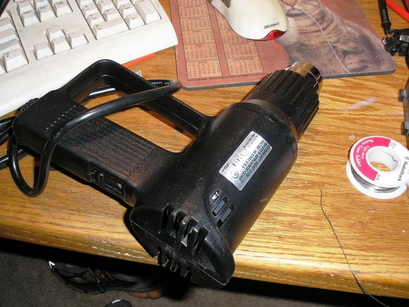
Heat Gun
Required Parts
Connectors to be Disassembled
Soldering Wire
Heat Shrink Tubing
OR 3M Electrical Tape (Super 33+ or 88+)
Procedure
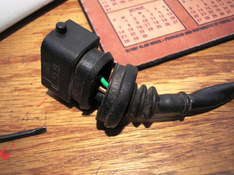
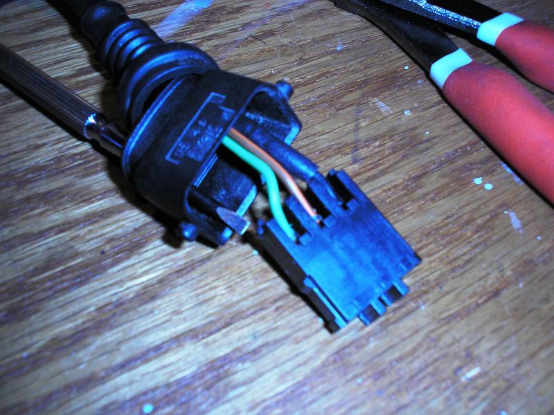
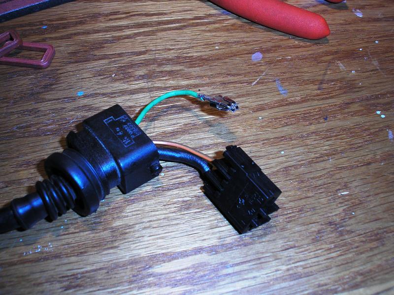
The first thing you will need to do is pull back the rubber boot from the connector, then chop off the connector you wish to work with. I suggest cutting the wires no more than 2cm from the connector terminal. Trim them to the desired length when you are reinserting the wires into the connector terminal. The connector shown in this article was from a spare harness, and was not used on any vehicle.

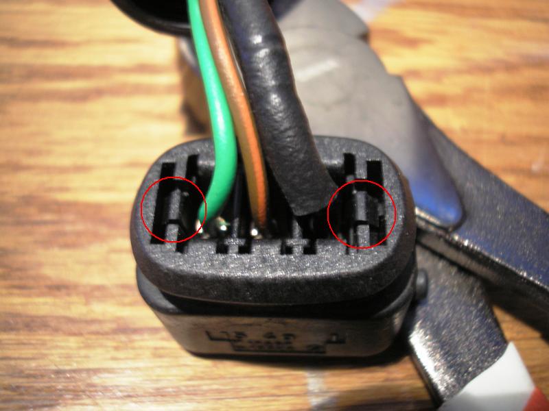
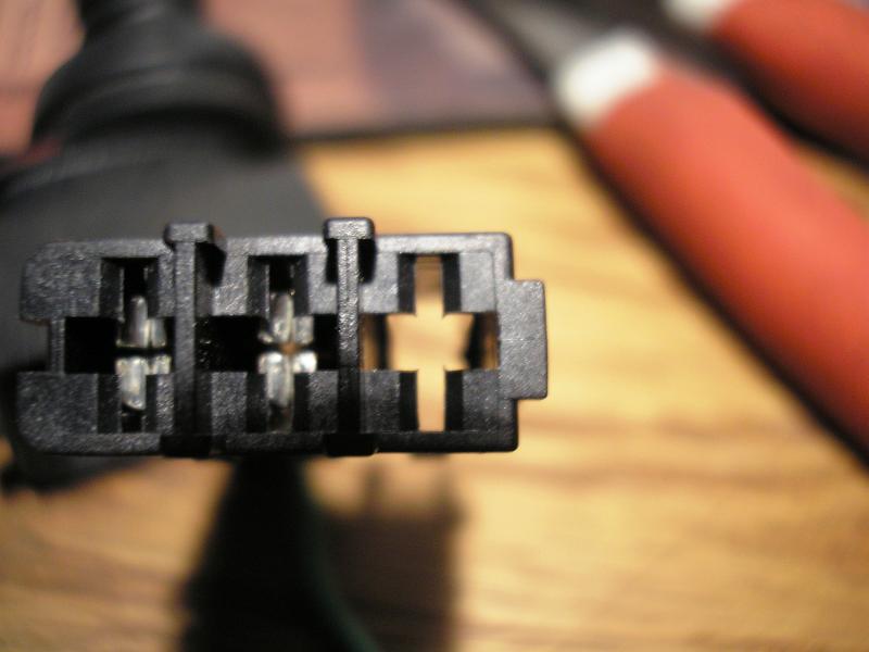
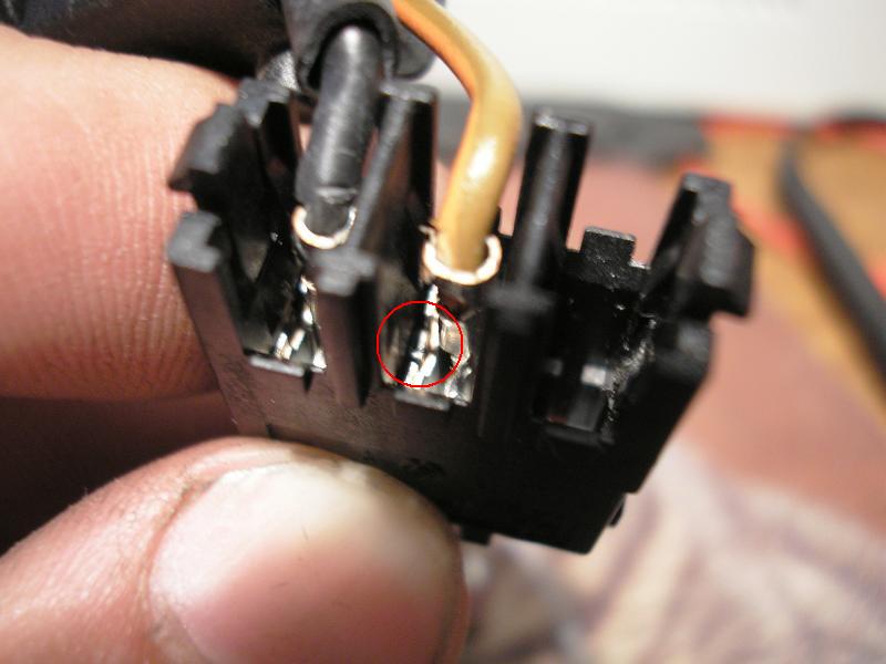
The next order of business is to remove the center section of the connector. There are two tabs at the sides of the connector's back (circled in red in the first picture). Using a small screwdriver you can pry these inward and push on them to get the center part out.
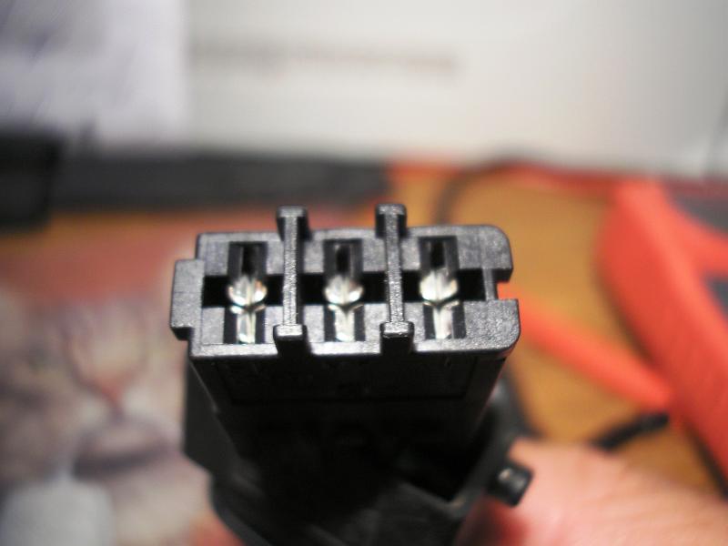
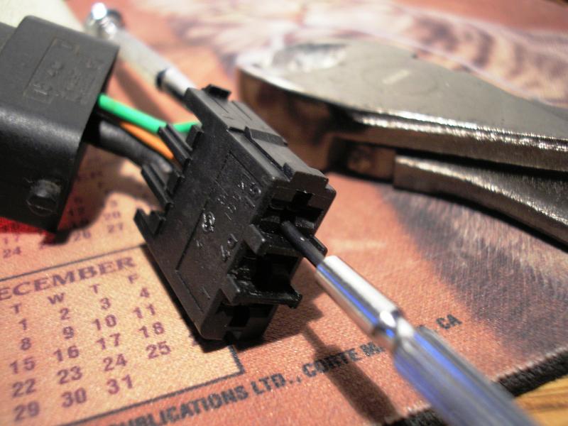
Here is the first tricky part. Using the second smallest screwdriver in the set, slide it into one of the two little slots beside the terminal fronts. Once in, turn it 90 degrees so that the flat-blade end is perpendicular to the terminal body (so the end forces the biggest gap possible, you will see why). With the turned screwdriver in there, take the smallest screwdriver (or one size larger, it is up to you) and insert it into the back of the connector on the same side as the other one. You should be able to see the first driver's end from the other side. Use the second one to hold down the little tab that the first oen was holding, then remove the first one. Reinsert it into the other slot on the front and turn it 90 degrees. Both tabs should now be pressed flat, and you can use the needle nose pliers to pull the terminal out of the body. It can take a fair amount of pulling force to remove.
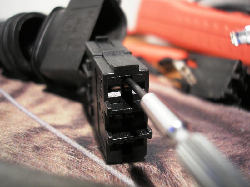
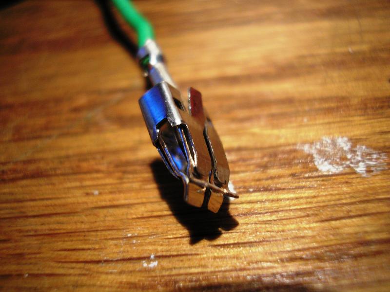
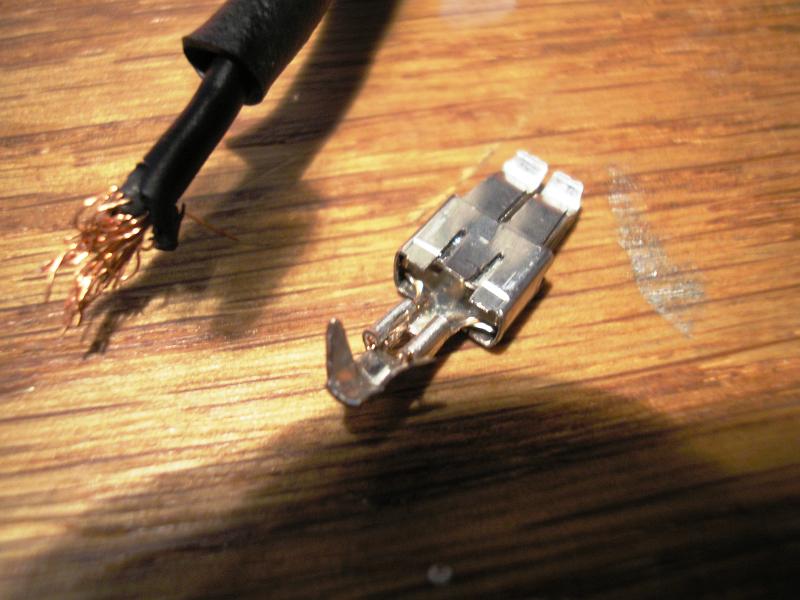
Take a look at these close-up pictures of the parts. They should help to clarify what needs to be done. You can see the two small raised tabs on the connector terminal that need to be pressed flat. Also take note of the small ledges within the connector body that the two tabs snap into (a little blurry). Finally, take note of the back side of the connector. The pressed tab is shown circled in red in the fourth picture.
Do this for all three termnials in the connector.
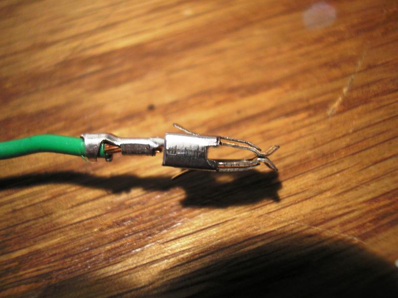
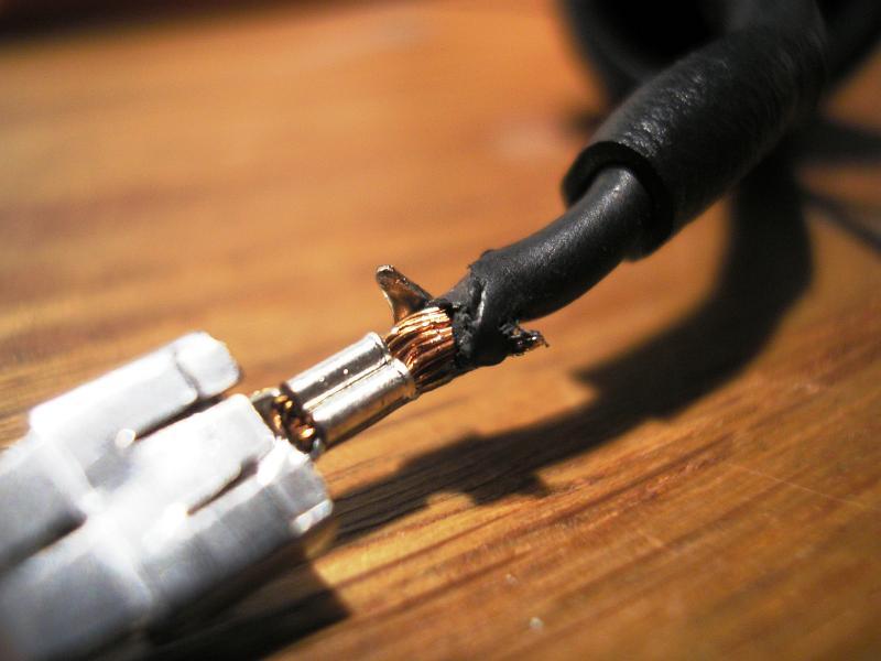
Here begins the next tricky part. You need to get the wire out of the terminal, and it is crimped in. There is no way to do this perfectly, but done right the terminal can be reused easily. Take a good look at how the wire is secured. There are two small prongs that hold it around the insulation, and then two more flaps folded tightly over the exposed copper. Begin by using the second smallest screwdriver and needle nose pliers to pry the two smaller prongs off of the insulation. Next is the hard part.
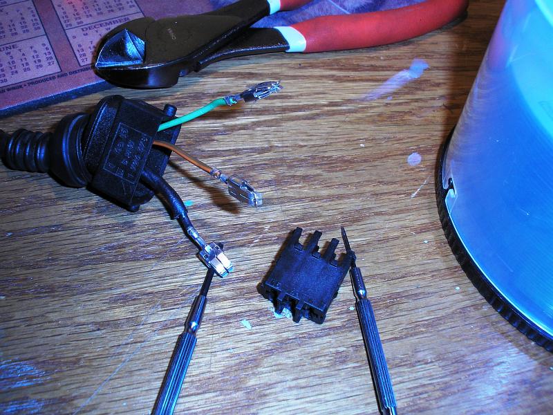
You will take the third smallest screwdriver and position its blade between the two folded flaps. Make sure the terminal is on a hard surface that you will not mind putting scrapes in. Hit the end of the screwdriver a few times with a very small hammer or your wire cuters. You do not need much force. You simply need enough to get the flaps spread. I found that smacking the screwdriver THROUGH the terminal made things far easier (you can see the hole in the third picture). You get more room to use the blade to pry on the folded flaps that way. Pry on them as hard as you can without deforming the rest of the terminal body. Wiggle the wire in curcular and twisting motions and most of the wires will wriggle out. You will likely not be able to get all of them out, but that is fine. One last tip is to set the terminal on a rounded edge of a table so the part the screwdriver will hit is flat against a hard surface. The connector will bend a little if you do this on a flat surface.
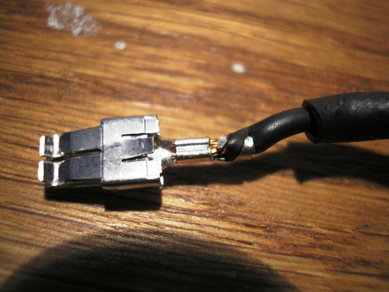
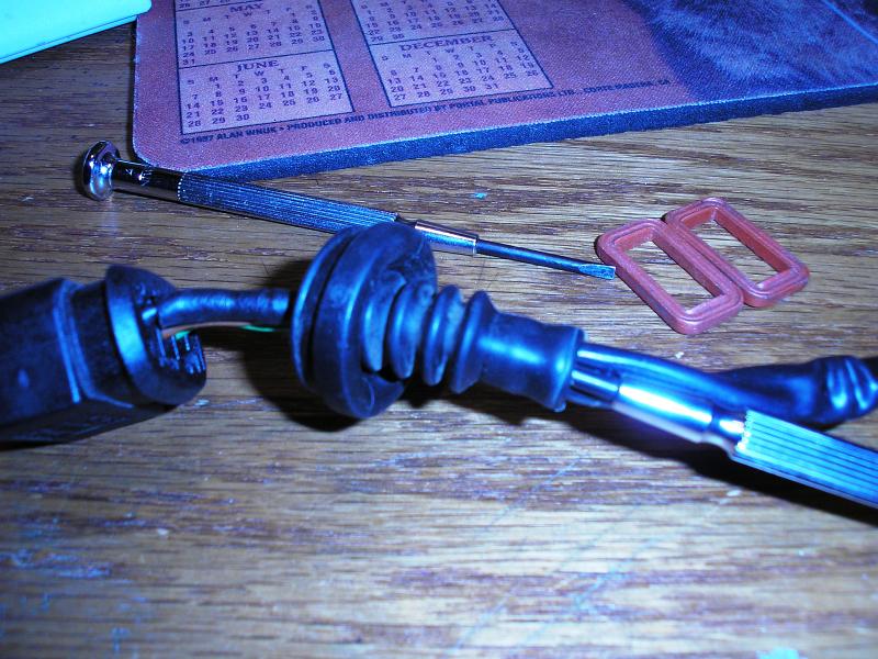
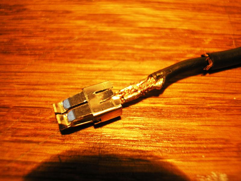
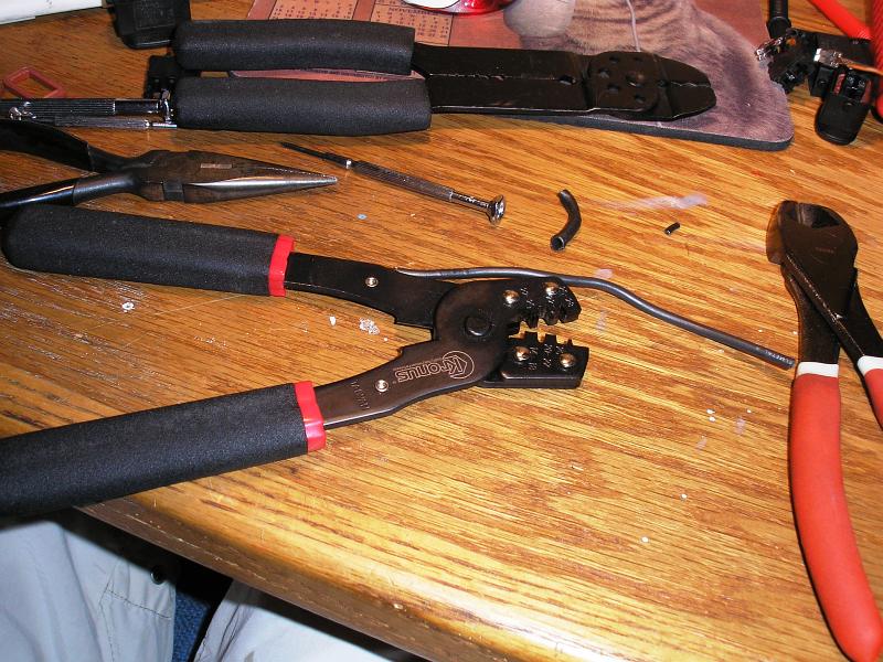
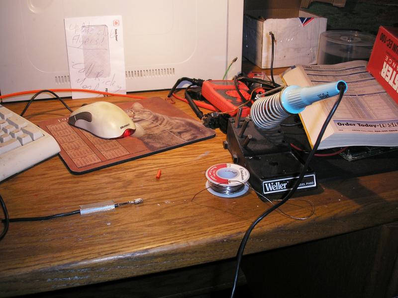
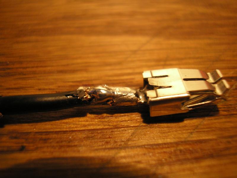
Trim the wires on your harness to the desired length, leaving enough that it will not be a stretch to reach their destination. Strip about 4mm of insulation off the wire ends. Reinsertion will require a terminal crimping tool. It can be done with pliers, but it is very difficult and there is an increased risk of destroying the terminal. The crimping tool, as seen in the second picture, can be purchased at most Radio Shack stores for under $10. Just make sure the crimping teeth look exactly like the ones in the picture, other types of crimpers will not work for this! Once you have crimped the wire back in, it should look like the first picture. You will need to use a few passes with various slots on the crimper to get it well secured. Once you have done this, you can make it a more permanent installation with some solder. Be sure to solder ONLY the wire in the terminal. Do not get it on the free portion of the wire as the solder makes it a brittle joint: the wire will eventually break off from engine vibrations.
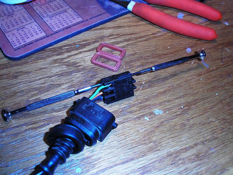
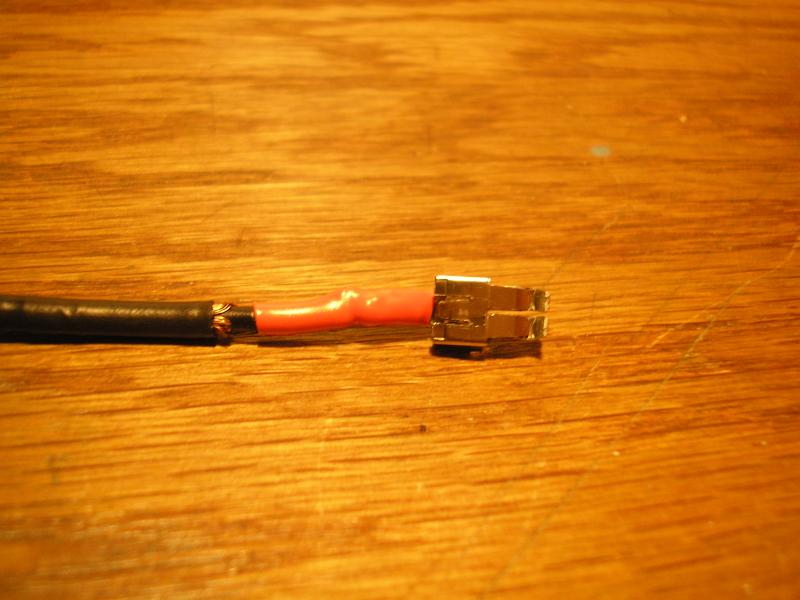
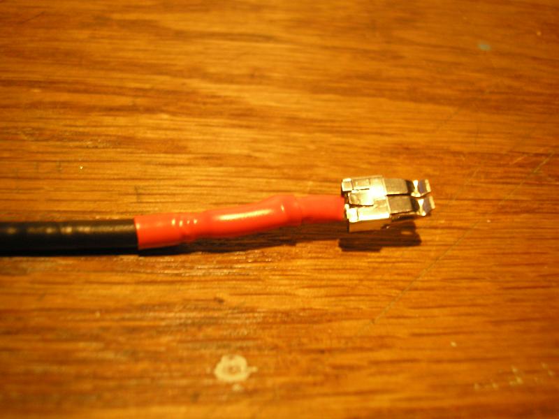
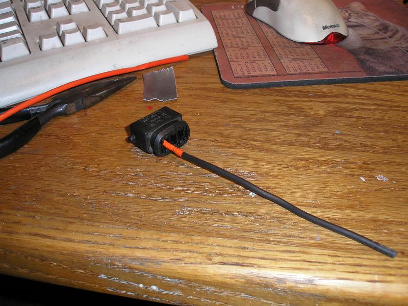
The final reconstruction step is weatherproofing. Electrical tape (3M Super 33+ or 88+) can be used. The preferred method is heat shrink tubing. Be sure to put the unshrunk tubing pieces on BEFORE you crimp the terminals back on, or you will be using electrical tape whether you like it or not. In the case of a shielded wire as shown below, use one piece on the terminal and another to cover the exposed shielding. A heat gun is needed to shrink the tubing. A hair dryer will not work.
This is the last step. Before reinserting the terminals into their plastic body, be sure to slide the large outer plastic body housing over the wires. It has to be slid on first because of the direction in which the terminal body goes into it. Reinsert the terminals into the body, and slide the body back into the housing. Just in case you forgot which wire went where, the black shielded one goes in spot 1, the brown/yellow one goes in 4a, and the green one goes in 15. All done!
DISCLAIMER: I take no responsibility (and thus I cannot be held responsible) for damages and/or injuries caused by attempting the procedures outlined on this site. The information provided is to be used at the reader's discretion and all necessary safety precautions requiring emplacement (mentioned or not) are the responsibility of the reader.